BsidesKC 2025 - Spinning Top Kit
Welcome to the Learn to Solder Village! Follow the steps carefully, paying special attention to components with polarity (led's, transistors). Before you begin, test your LEDs using a CR2032 battery to ensure they work by putting the anode (longest pin) on the top (+) side of the battery and the cathode (short pin) on the bottom (-).
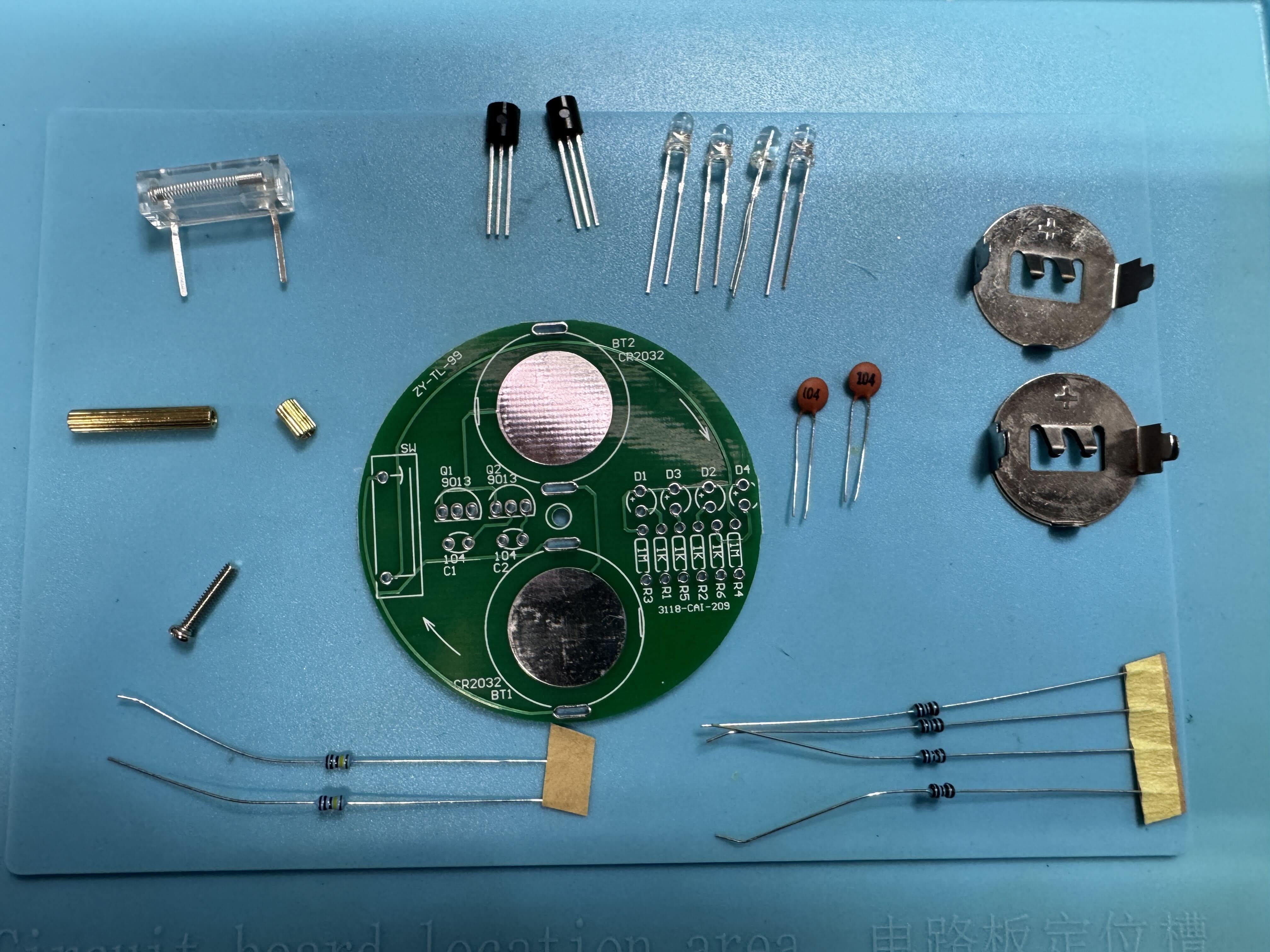
Tools Needed
- Soldering iron
- Solder
- Wire cutters
- Tweezers (optional)
Safety Tips
- Work in a well-ventilated area
- Wear safety glasses
- Be cautious: the soldering iron tip is extremely hot
- When trimming the leads off of the components with the flush cutters make sure to hold on the the pin so that it doesn't fly away!!
Component Installation
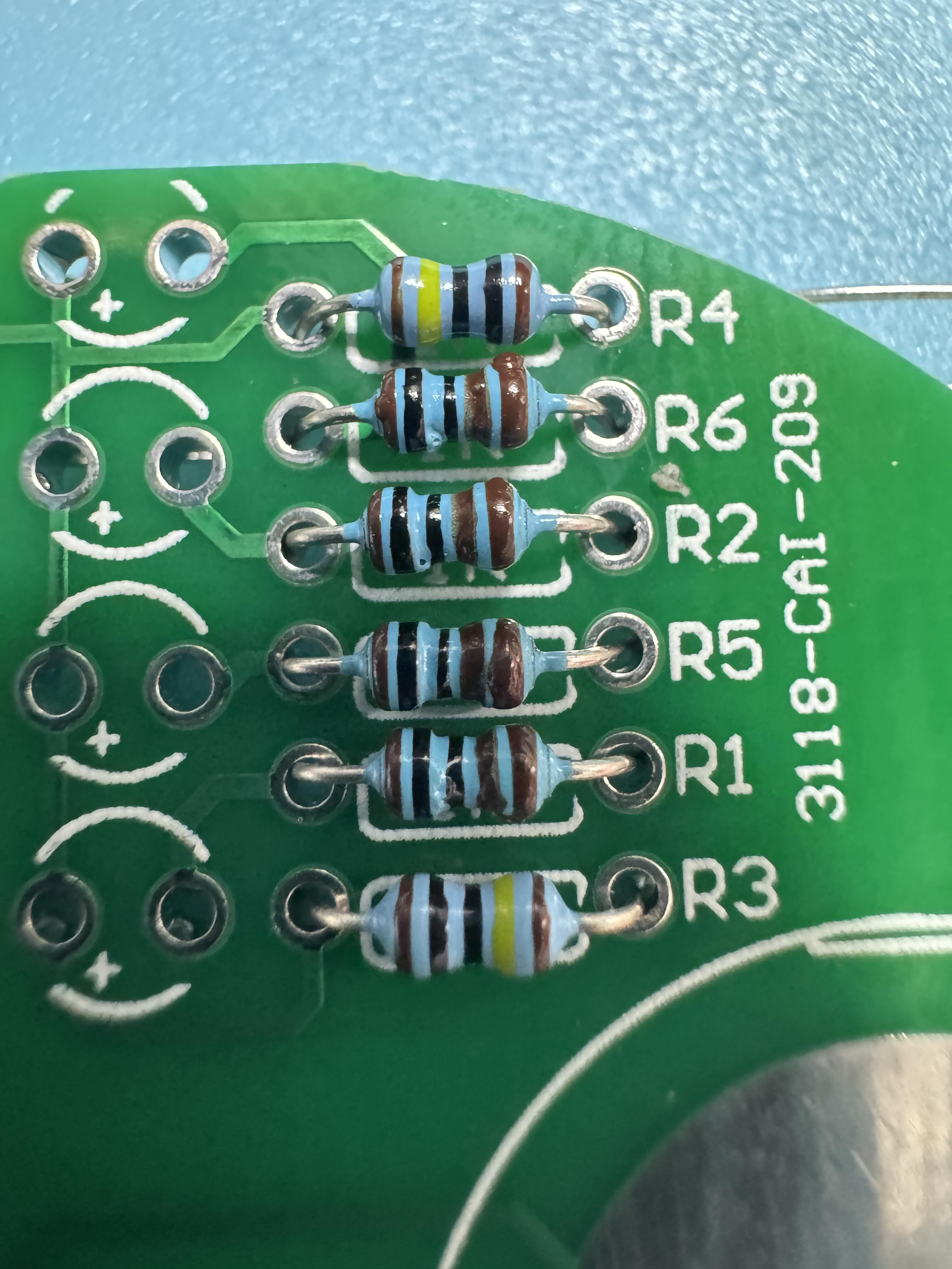
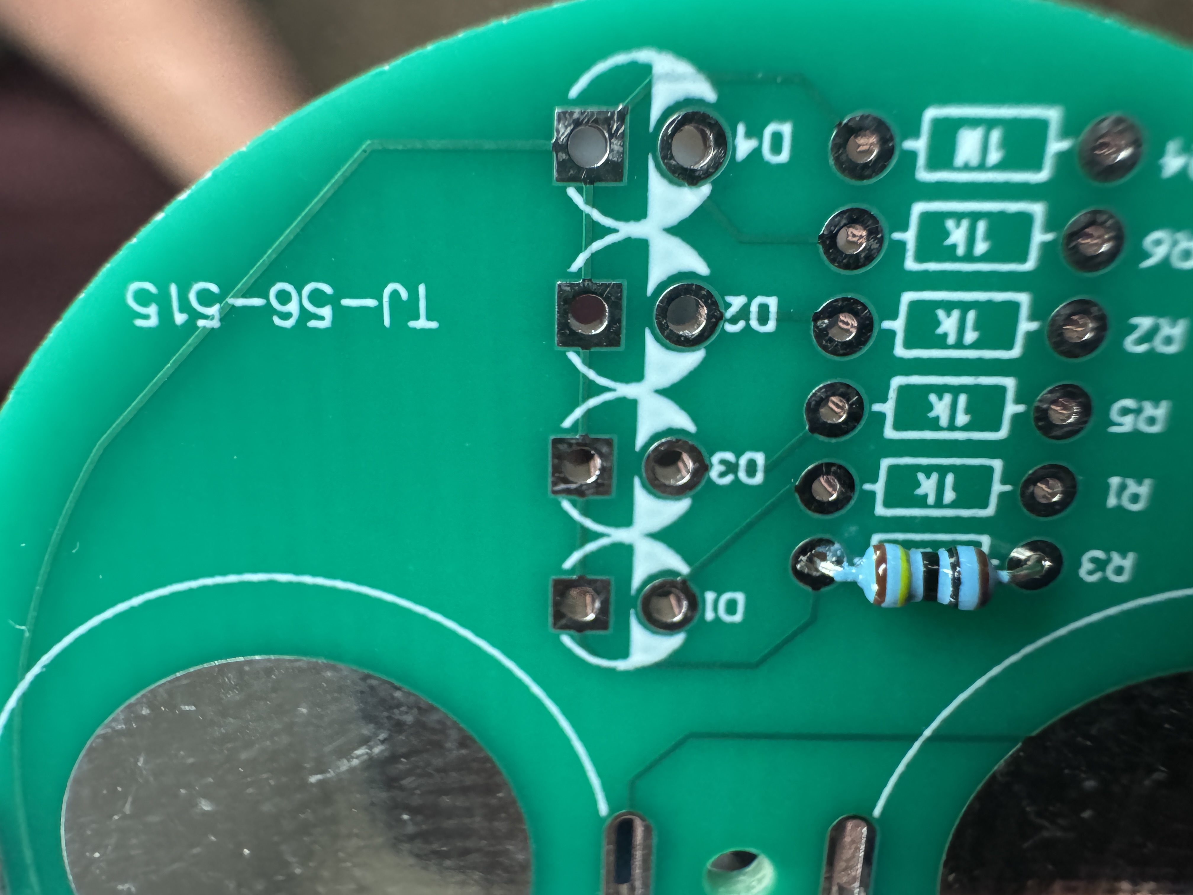
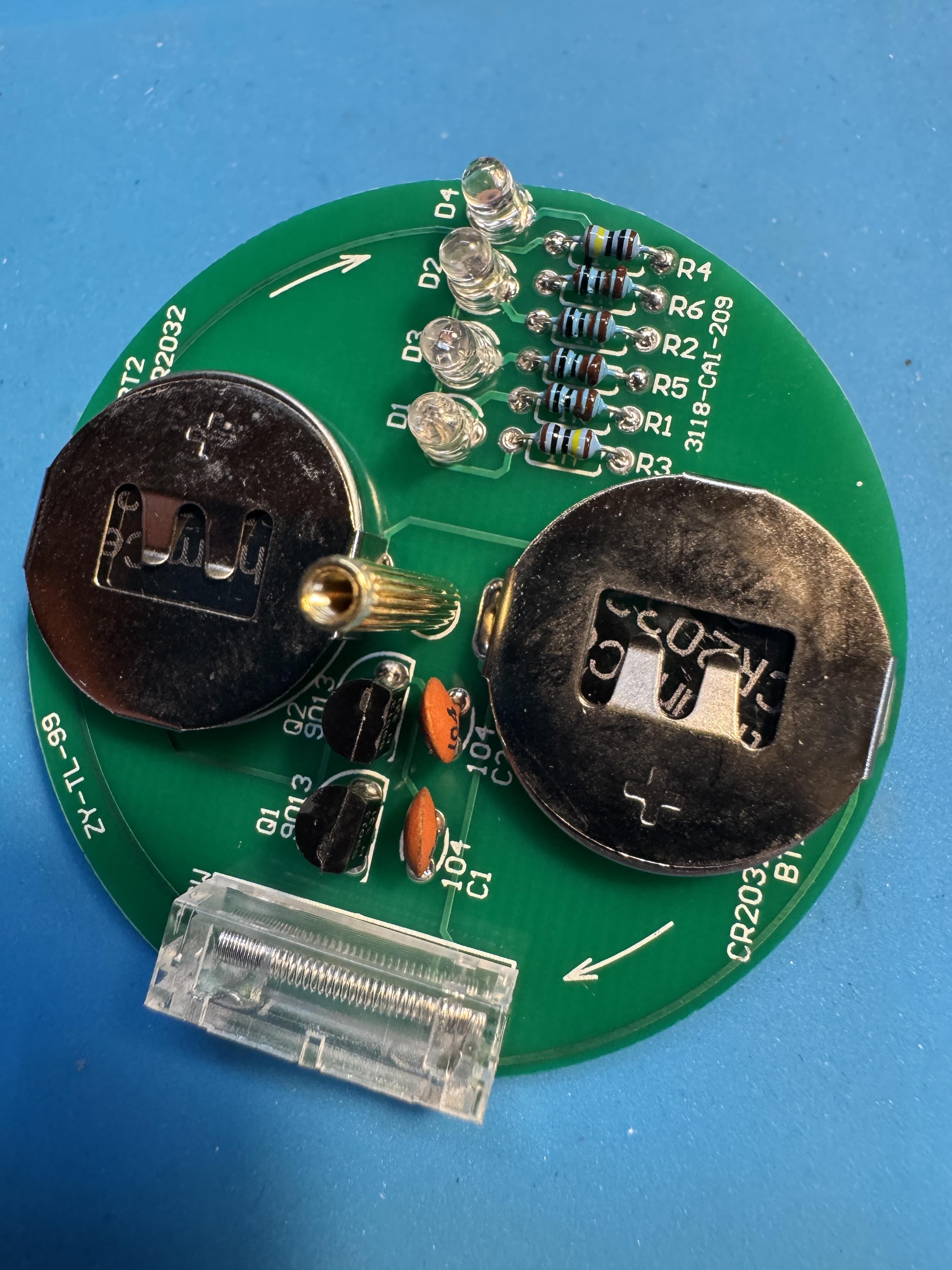
1. Resistors
The resistors come packaged as a group of 2 (1M) and a group of 4 (1K) ohm and it is important they are installed in the correct locations
1MΩ Resistors (R3, R4) (Qty 2)
- No polarity
- Install the 1MΩ resistors in the locations marked R3 and R4
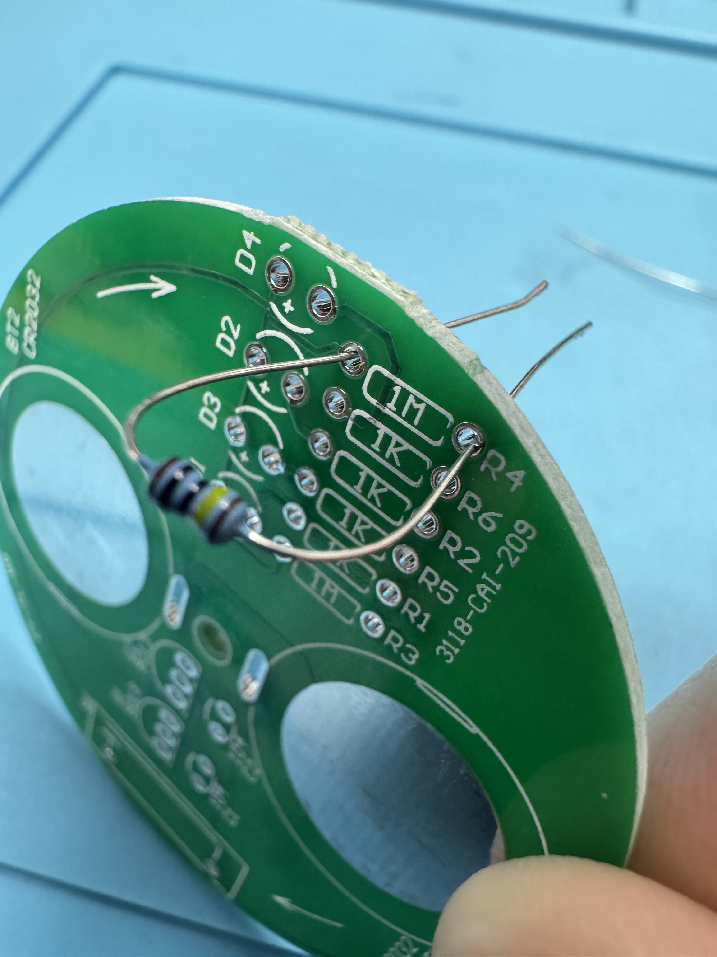
1kΩ Resistors (R1, R2, R5, R6)
- No polarity
- Install the 1kΩ resistors in the locations marked R1, R2, R5, and R6 on the PCB
2. Battery Clips
Button Battery Clips (BT1, BT2)
- Polarity matters
- Make sure the clips are installed in the correct orientation otherwise the components on the board will prevent you from inserting the battery!! The silkscreen on the PCB has a notation on it to indicate where the backside (closed) side of the battery holder goes.
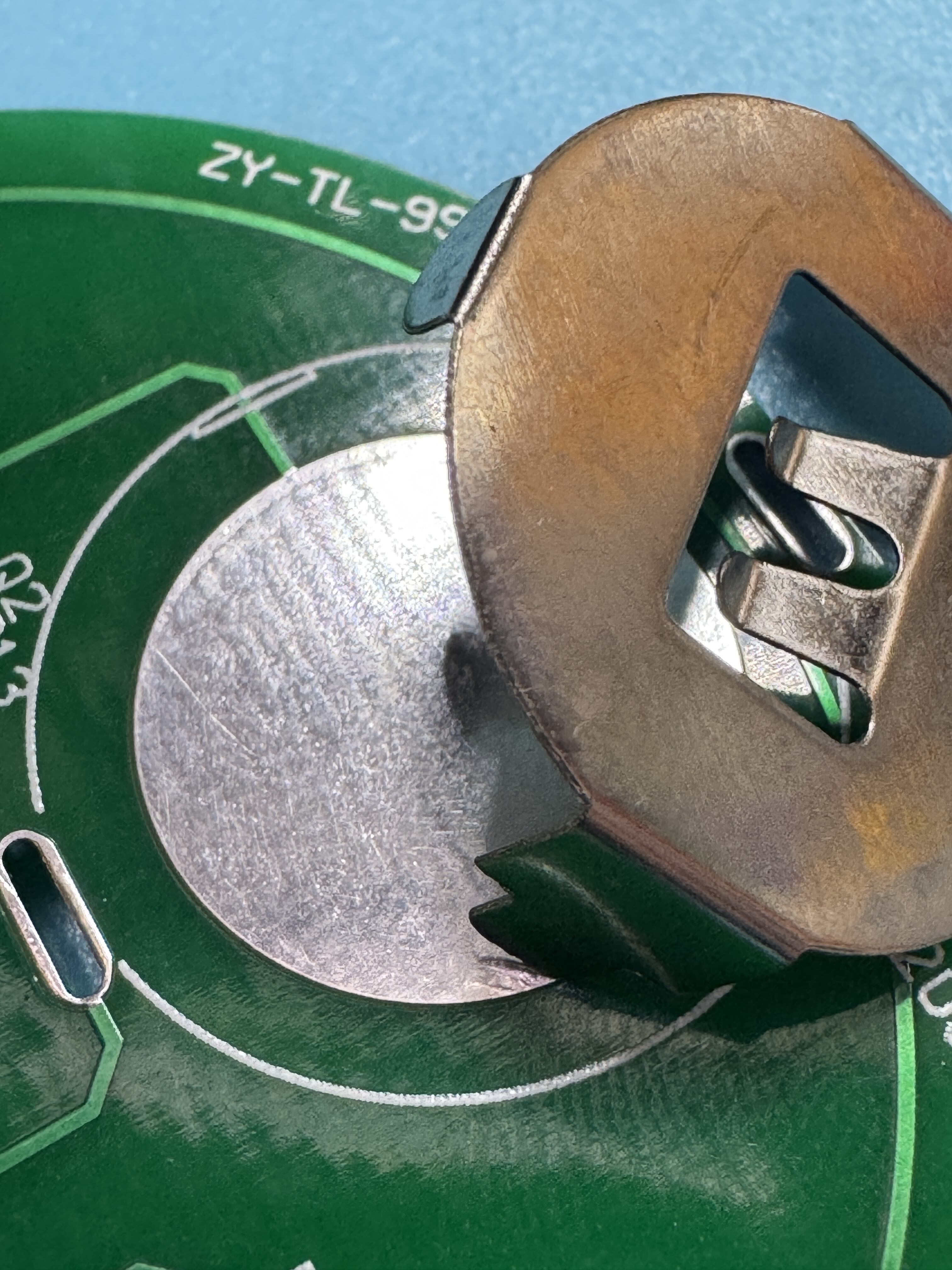
--
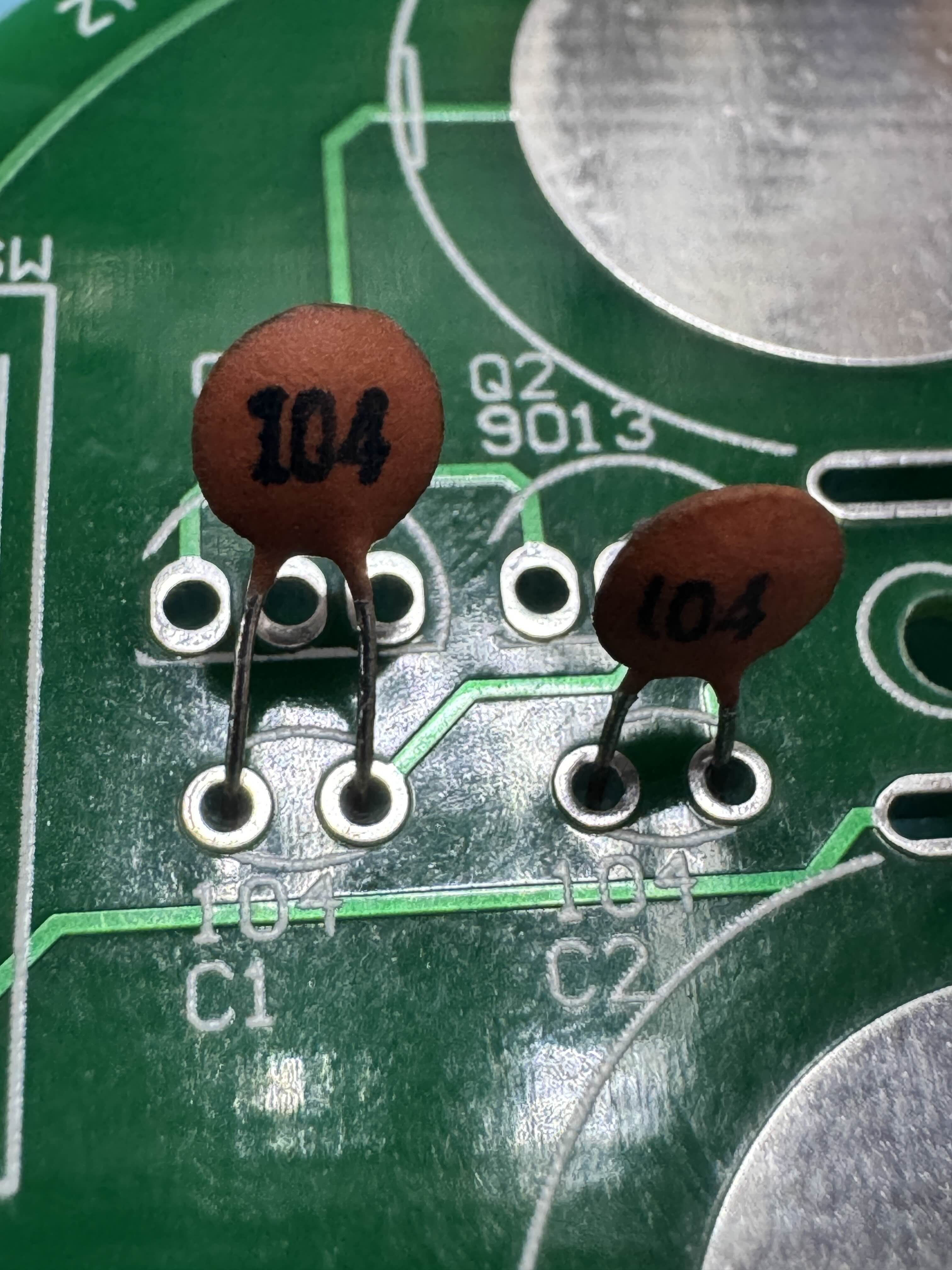
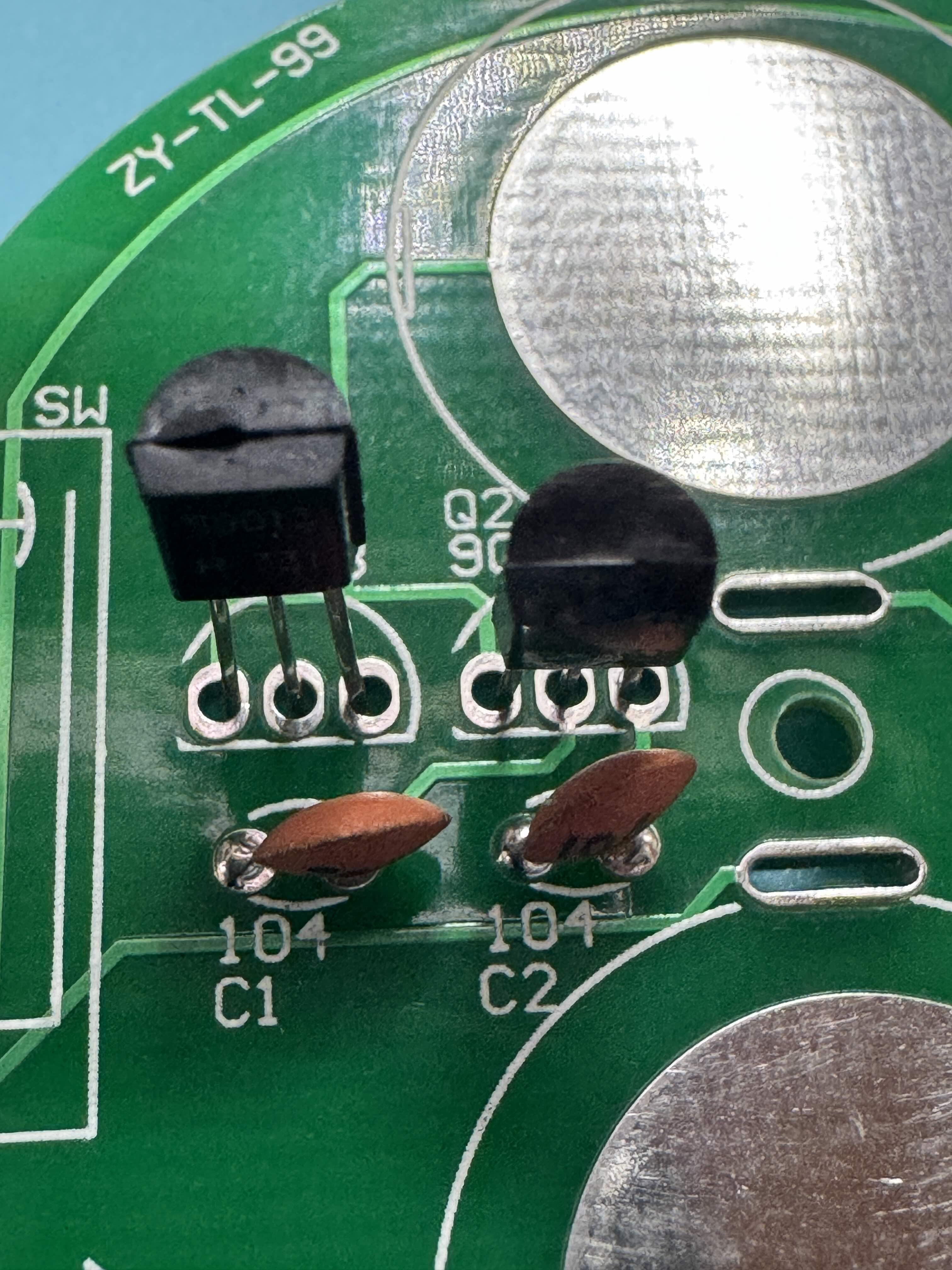
3. Capacitors
0.1μF Capacitors (C1, C2)
- No polarity
- Install capacitors in the locations marked C1 and C2
4. Transistors
9013 Transistors (Q1, Q2)
- Polarity matters
- Match the flat side of the transistor with the marking on the PCB
5. LEDs
LED Diodes (D1, D2, D3, D4)
-
Polarity matters
-
Did you test your LED's? You should test your LED's! :)
- The longer lead is positive (anode) and should go to the pad marked with a '+'
- Test LEDs with a CR2032 battery before installing and chose your color layout
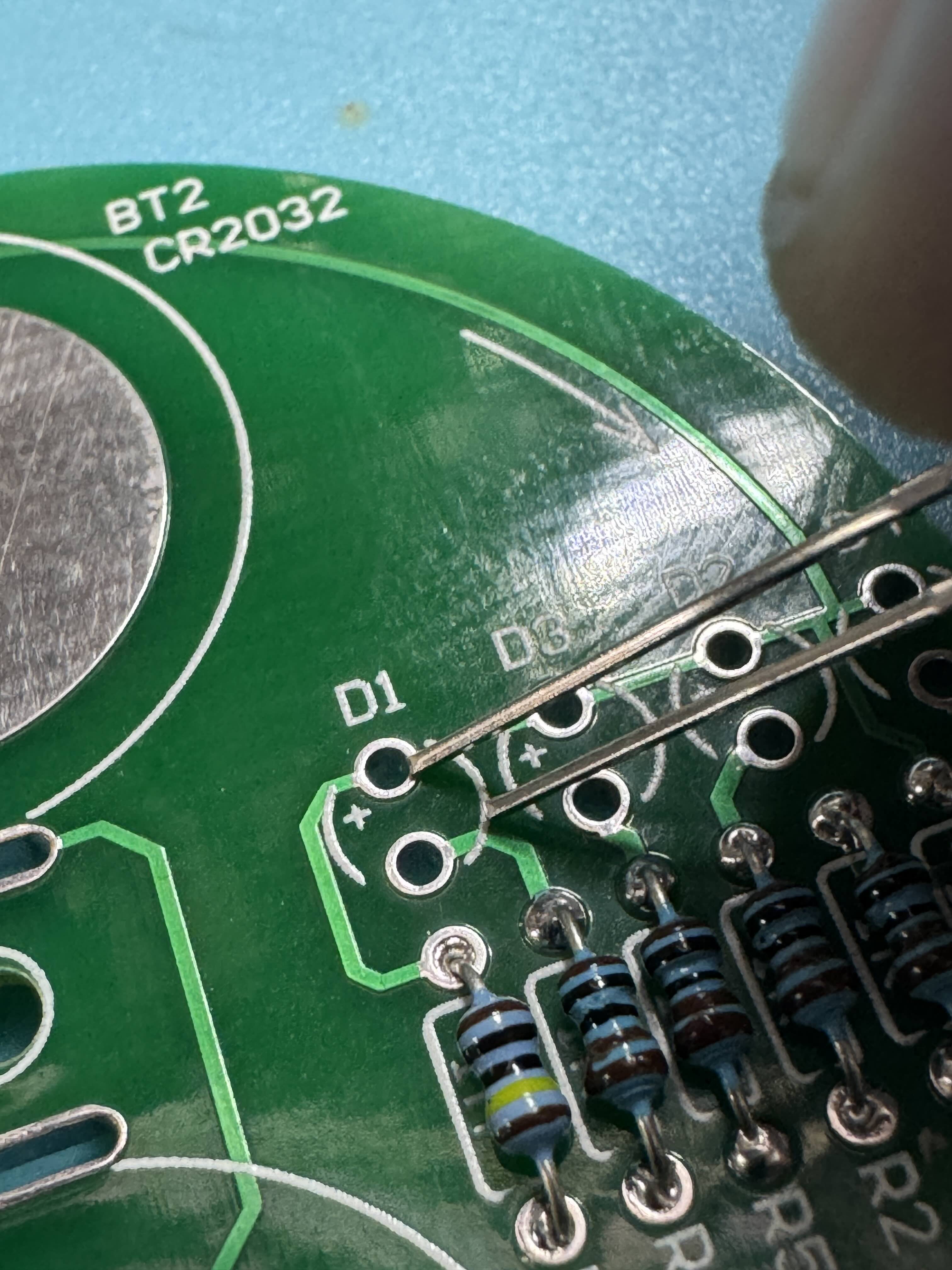
If your PCB looks like this the square is the positive through hole.
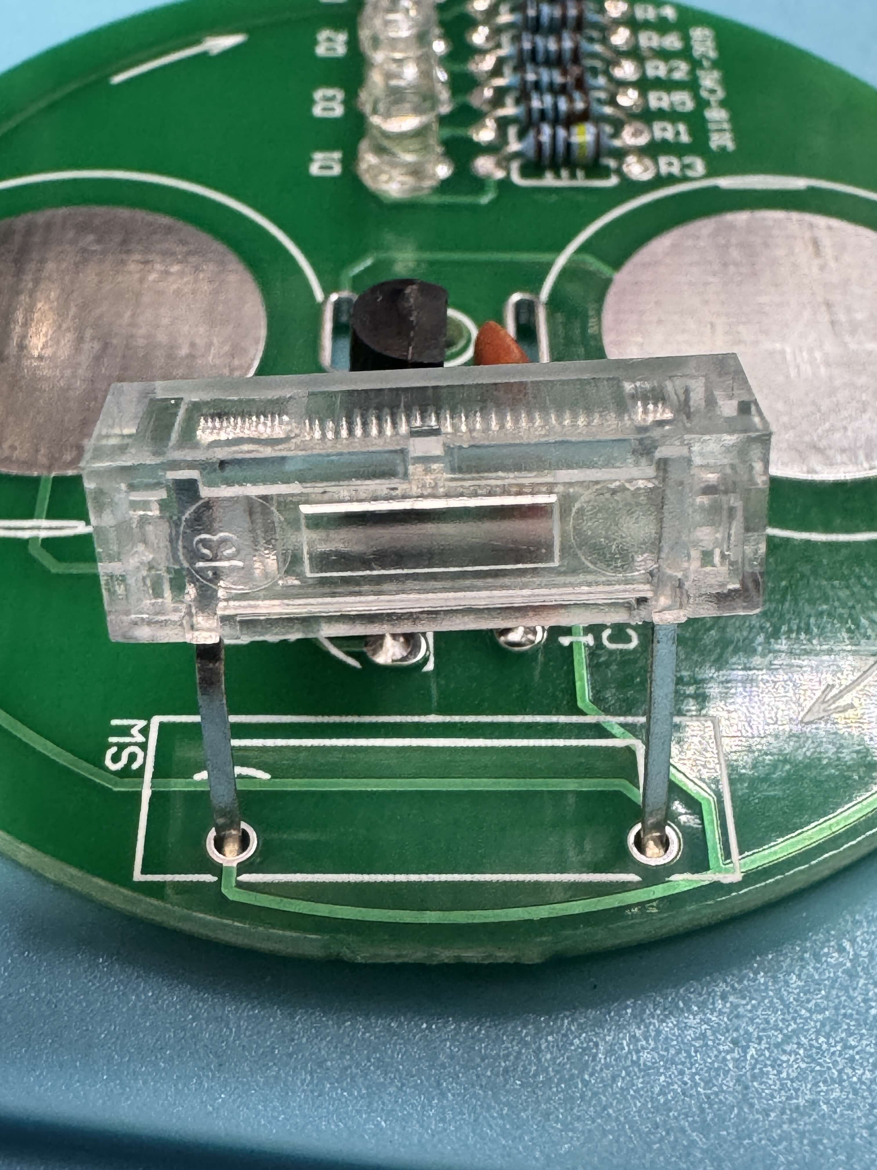
6. Switch
Switch (S1)
- Does have polarity and should be installed according to the silkscreen on the PCB to prevent interference with other components.
- Make sure it fits inside the rectangle on the silkscreen.
- Install the switch into the location marked S1
Final Assembly
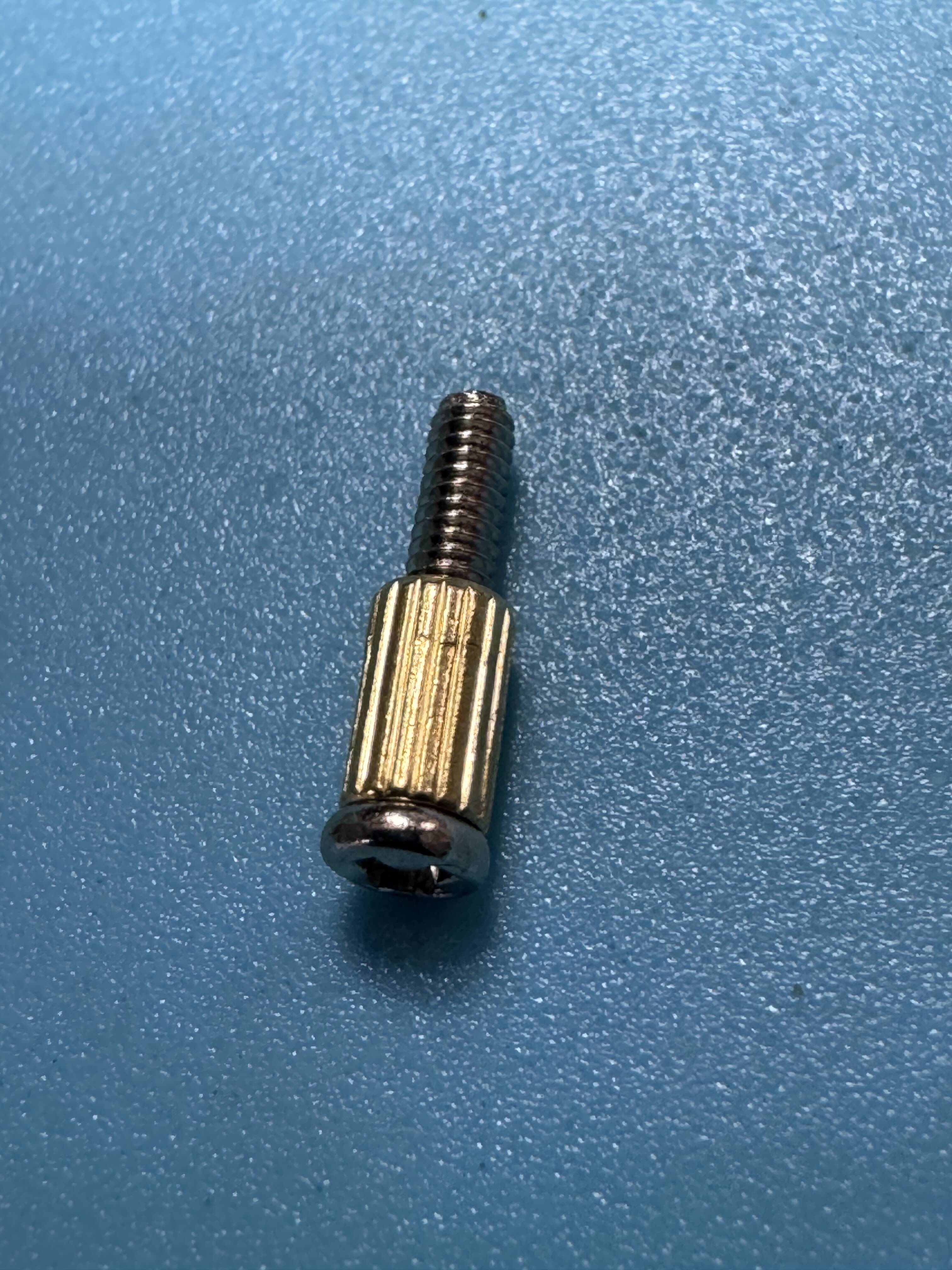
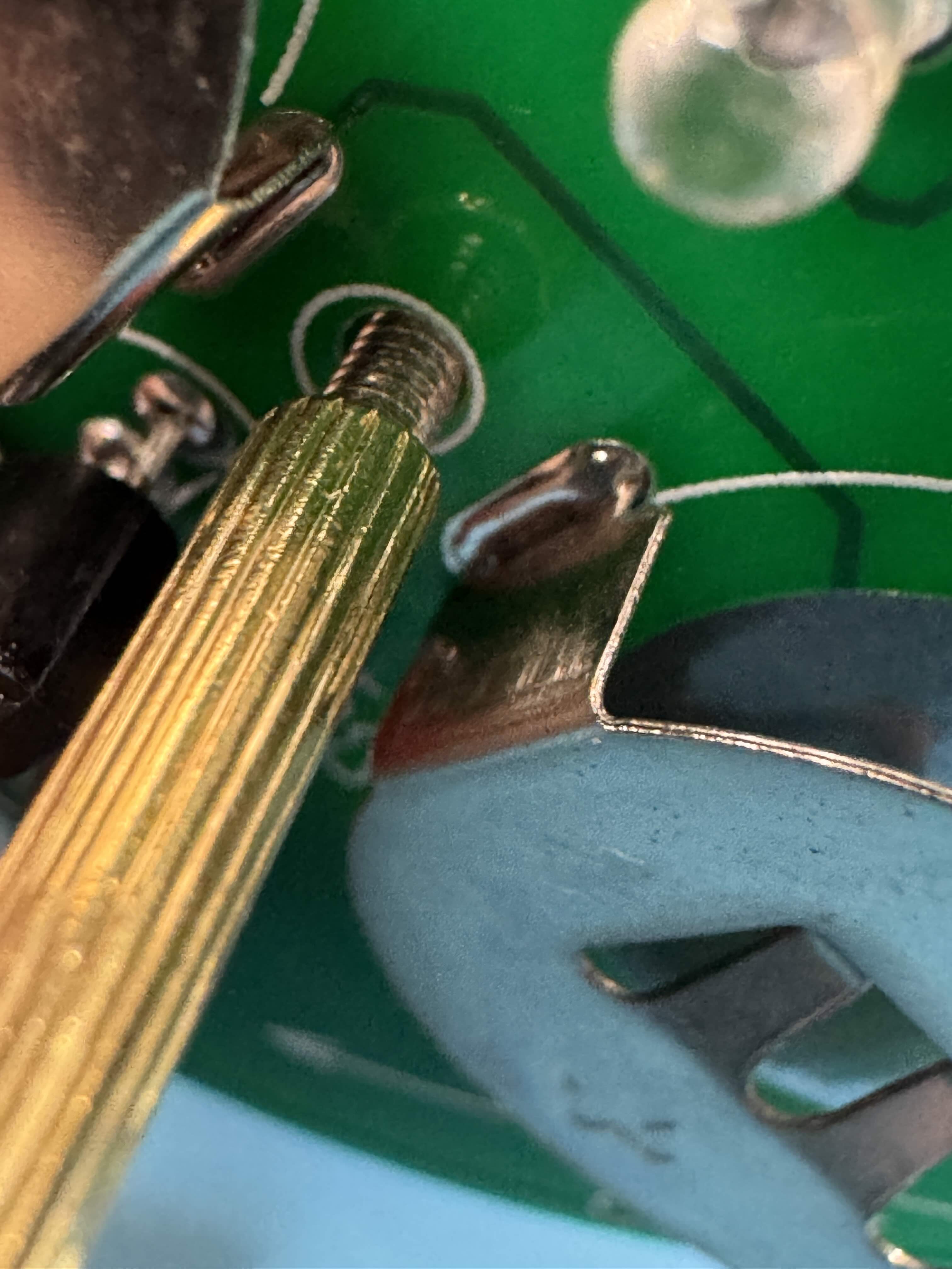
Mounting Hardware
Assemble the Top Handle
- Attach the small M28 copper pillar to the bottom of the board using the M210 screw
- Insert the assembly through the hole in the center of the PCB
- Screw the taller M2*18 copper pillar onto the top side to form the spinning handle
Assembled Kit
Powering Up
- Insert two CR2032 batteries into the clips, matching the '+' side with the markings on the board
- Spin the top and the LED's should illuminate when it has rotation.
Troubleshooting
- LEDs don't light: Double-check polarity and solder joints
- Top doesn't spin well: Check that the mounting hardware is tight and centered
Congratulations! You've completed your Spinning Top Kit!
Bill of Materials
| Component | Quantity | PCB Marker |
|---|---|---|
| 1kΩ Resistor | 4 | R1, R2, R5, R6 |
| 1MΩ Resistor | 2 | R3, R4 |
| 0.1μF Capacitor | 2 | C1, C2 |
| 9013 Transistor | 2 | Q1, Q2 |
| LED Diode | 4 | D1, D2, D3, D4 |
| Switch | 1 | S1 |
| Button Battery Clip | 2 | BT1, BT2 |
| PCB Board | 1 | - |
| M2*4 Copper Pillar | 1 | - |
| M2*18 Copper Pillar | 1 | - |
| M2*10 Screw | 1 | - |