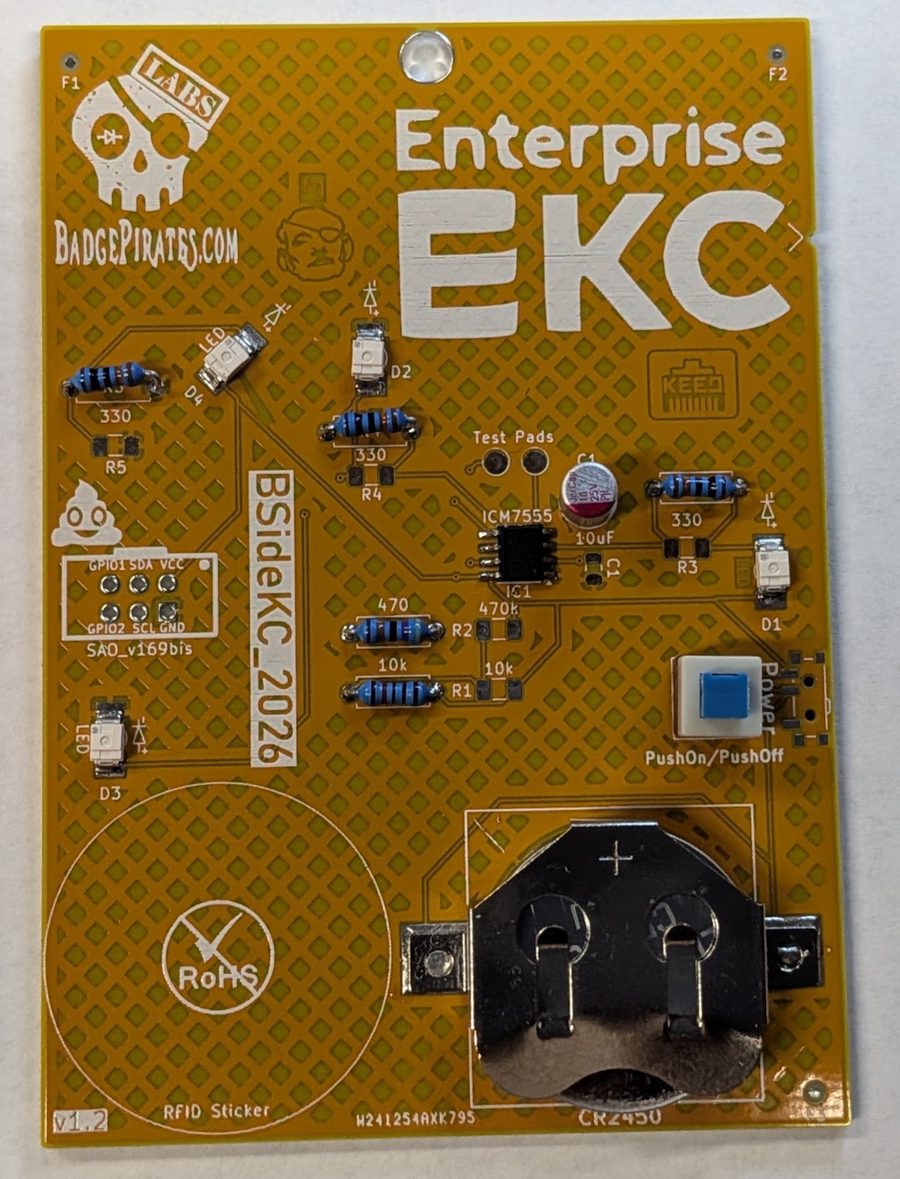
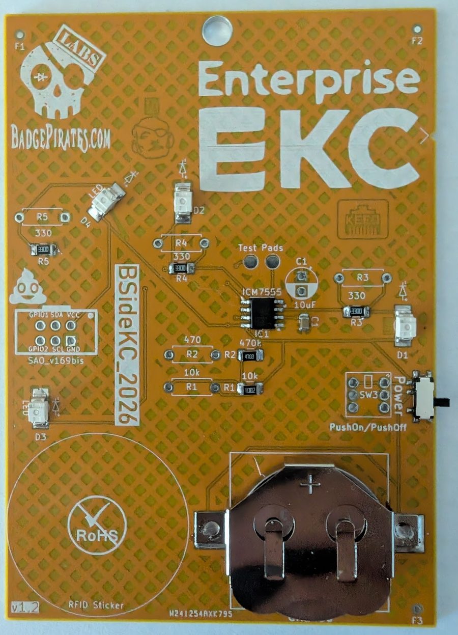
BSidesKC 2026 Badge Build Guide
This guide covers assembly of the BSidesKC 2026 badge, which comes in two versions: SMD (Surface Mount Device) and Through Hole. Both share a common set of components with version-specific differences for resistors and the switch.
Component List
Common to Both Versions
| Qty | Component |
|---|---|
| 3 | Yellow Reverse Mount LED |
| 1 | Red Reverse Mount LED |
| 1 | Battery Holder |
| 1 | 7555 Timer |
SMD Version
| Qty | Component | Marking |
|---|---|---|
| 1 | 10µF Capacitor | — |
| 3 | 300Ω Resistor | 3300 |
| 1 | 470Ω Resistor | 4703 |
| 1 | 10kΩ Resistor | 1002 |
| 1 | Slide Switch | — |
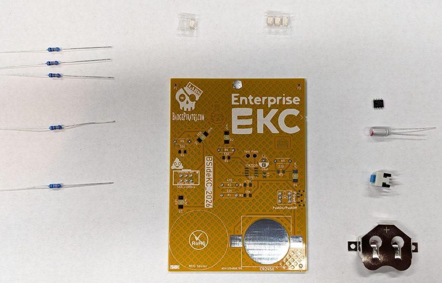
Through Hole Version
| Qty | Component | Color Code |
|---|---|---|
| 1 | 10µF Capacitor | — |
| 3 | 300Ω Resistor | Orange, Orange, Black, Black, Brown |
| 1 | 470Ω Resistor | Yellow, Violet, Black, Black, Brown |
| 1 | 10kΩ Resistor | Brown, Black, Black, Red, Brown |
| 1 | Push Button Switch | — |
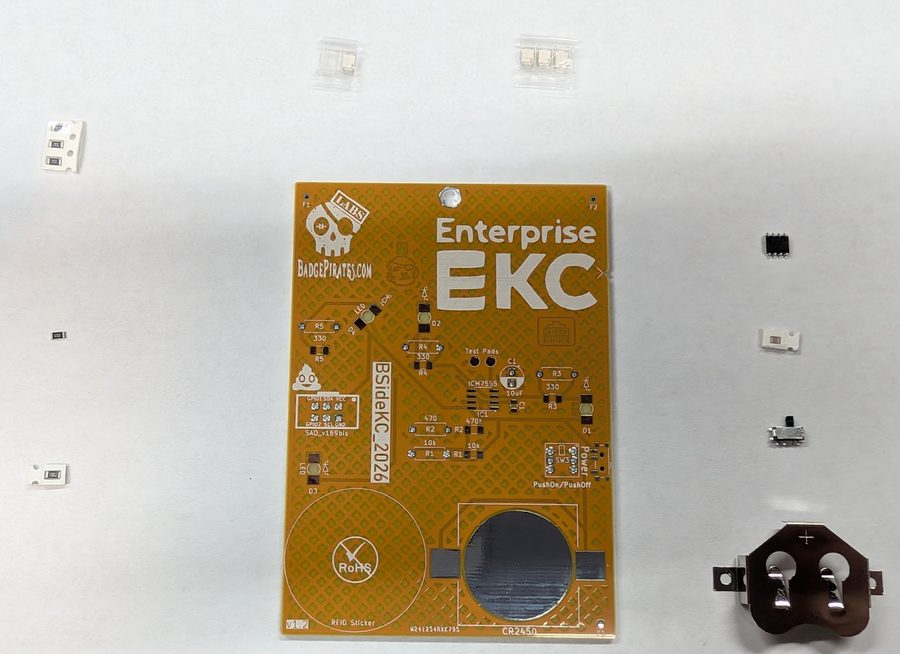
Assembly — Both Versions (SMD First)
Regardless of which version you're building, start with the SMD components. It's easier to solder the surface mount parts before adding through hole parts.
Step 1 — Apply Solder Paste
Apply paste to the pads for:
- Each LED
- All 8 pins of the 7555 Timer
- Side pads of the Battery Holder (skip the center round pad)
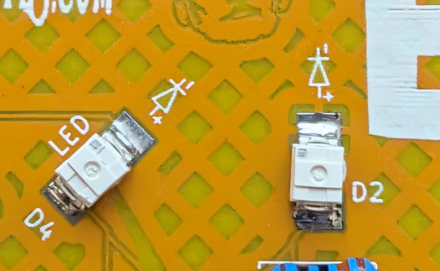
Step 2 — Place the LEDs
- Place the Red LED on the diagonal LED position, with the dot on the LED pointing up (toward the top of the board).
- Repeat for all 3 Yellow LEDs.
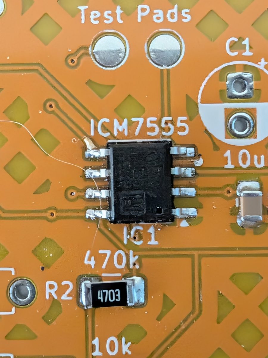
Step 3 — Place the 7555 Timer
The chip has a dot marking pin 1. Match this dot to the corresponding dot on the board's silkscreen — located in the lower right of the component footprint.
Step 4 — Place the Battery Holder
Set the battery holder on its pads.
Step 5 — Solder the SMD Components
Using a hot air station, reflow oven, or soldering iron, solder each pad. Work slowly — heat each pad until the solder melts rather than rushing.
SMD Version — Continue Here
Through Hole builders: skip ahead to the Through Hole section below.
Continue with paste, placement, and soldering for the remaining SMD components in this order:
- 1x 10µF Capacitor
- 3x 300Ω Resistors — marked
3300 - 1x 470Ω Resistor — marked
4703 - 1x 10kΩ Resistor — marked
1002 - Slide Switch
- Install the battery and power on.
Through Hole Continuation
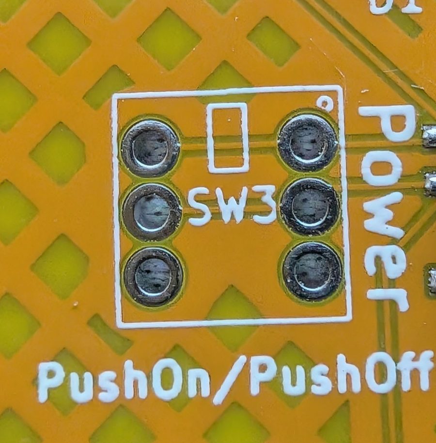
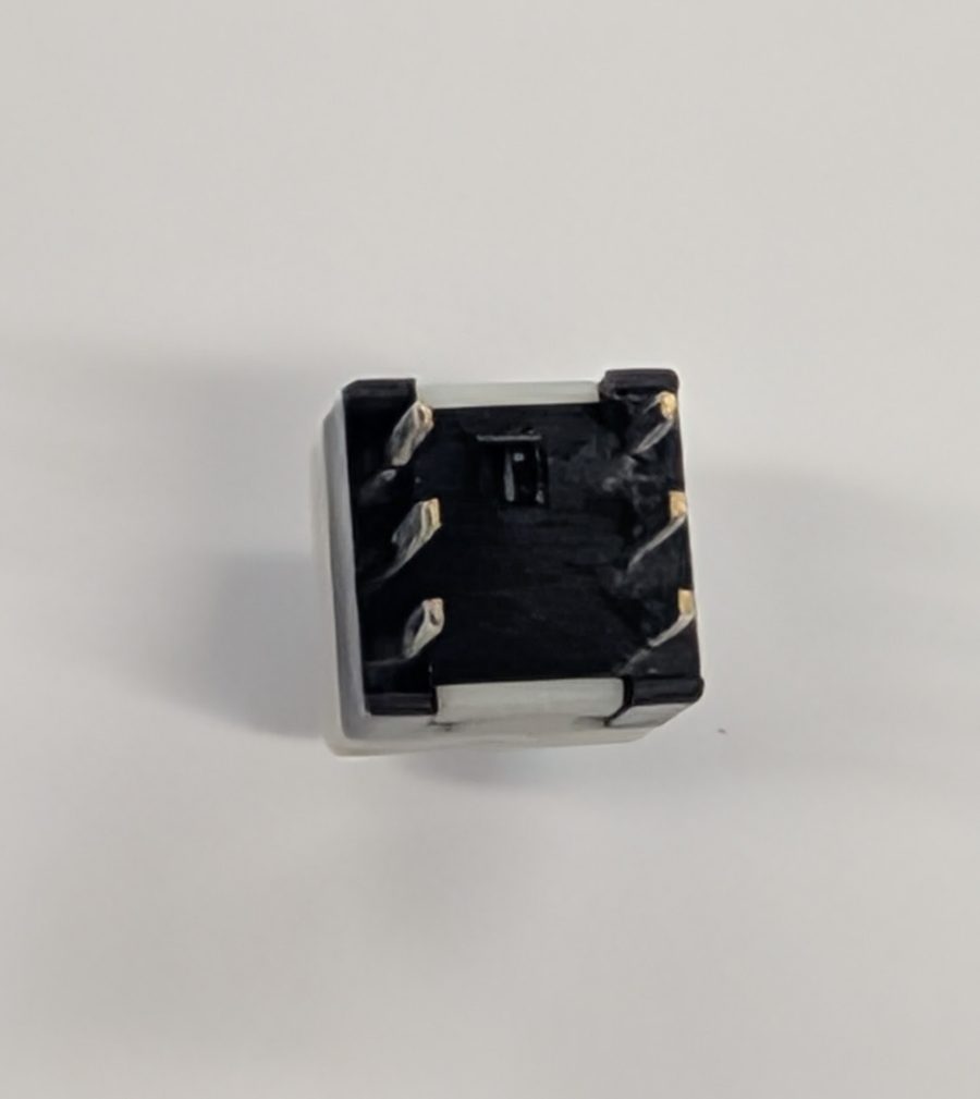
Step 1 — Place the Switch
Look inside the switch body — you'll see a small box on the top side. Match this box to the silkscreen box on the board. Place and solder.
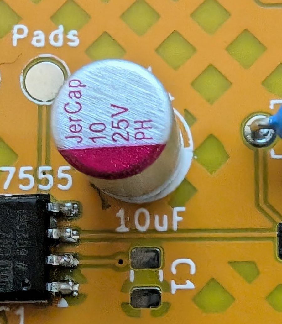
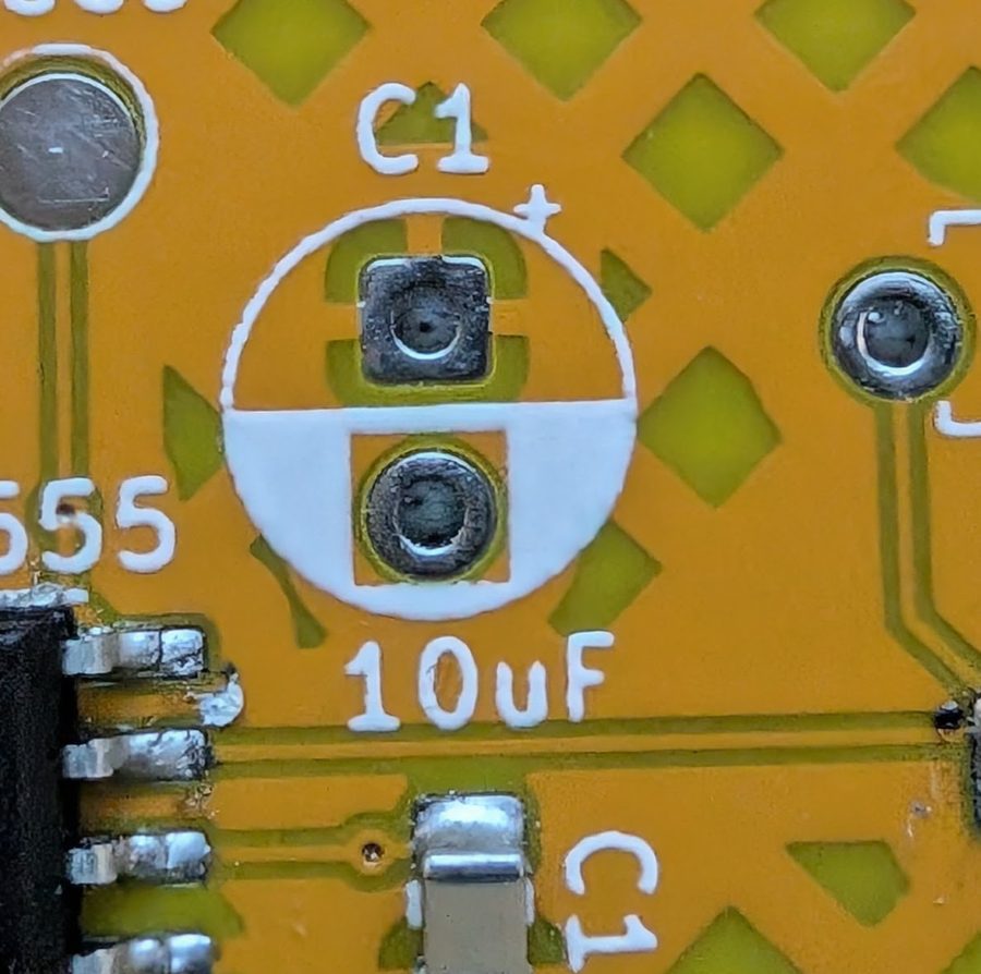
Step 2 — Place the Capacitor
The red stripe on the capacitor matches the white-filled side of the capacitor outline on the silkscreen. Place and solder.
Step 3 — Place the Resistors
Direction does not matter for resistors. Place and solder in any order:
- 3x 300Ω resistors
- 1x 10kΩ resistor
- 1x 470Ω resistor
Step 4 — Power On
Install the battery and turn it on.